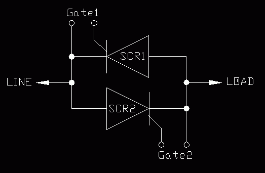
| There are three failure modes of an SCR: |
- No Conduction - looks like an open circuit
- Half-wave Conduction - looks like a diode
- Full-wave Conduction - looks like a short
|
| No Conduction: |
- Under very heavy short circuit currents the contacts between the case of the SCR and the SCR chip are blown like fuses and there is no connection thus no conduction.
|
| Half-wave Conduction: |
- Under certain conditions, junction damage or manufacturing defects can make the SCR look like a diode that conducts in one direction only. This often appears to be an intermittent problem that occurs when the SCR is hot.
|
| Full-wave Conduction: |
- Under moderate short circuit currents the SCR junctions are damaged and current usually flows in both directions (full-wave conduction). This type of junction damage can also occur due to high voltage spikes in the line voltage. Usually only one of the SCRs is shorted.
|
| The following chart shows various measurements you can make with a multimeter to determine if the SCRs are damaged. All voltages readings are taken on the output of the dimmer. Be sure a load is connected to the dimmer. Preferably one you can see. One voltage reading is taken with meter set to read AC volts and the other with it set to read DC volts. Be sure to disconnect the meter when switching between voltage settings or you may damage your meter. Several of the tests require that you run the signal from 0 to full and take readings at both ends. For example using the first test (Dimmer Operation is OK), when the signal goes from 0 to Full, the AC voltage should go from 0 to nearly line voltage and the DC voltage should remain close to 0.
|


